Spur Gear Calculator
Enter the module or diametral pitch, the number of teeth and the pressure angle to get every gear dimension, or work out the module of an existing gear.
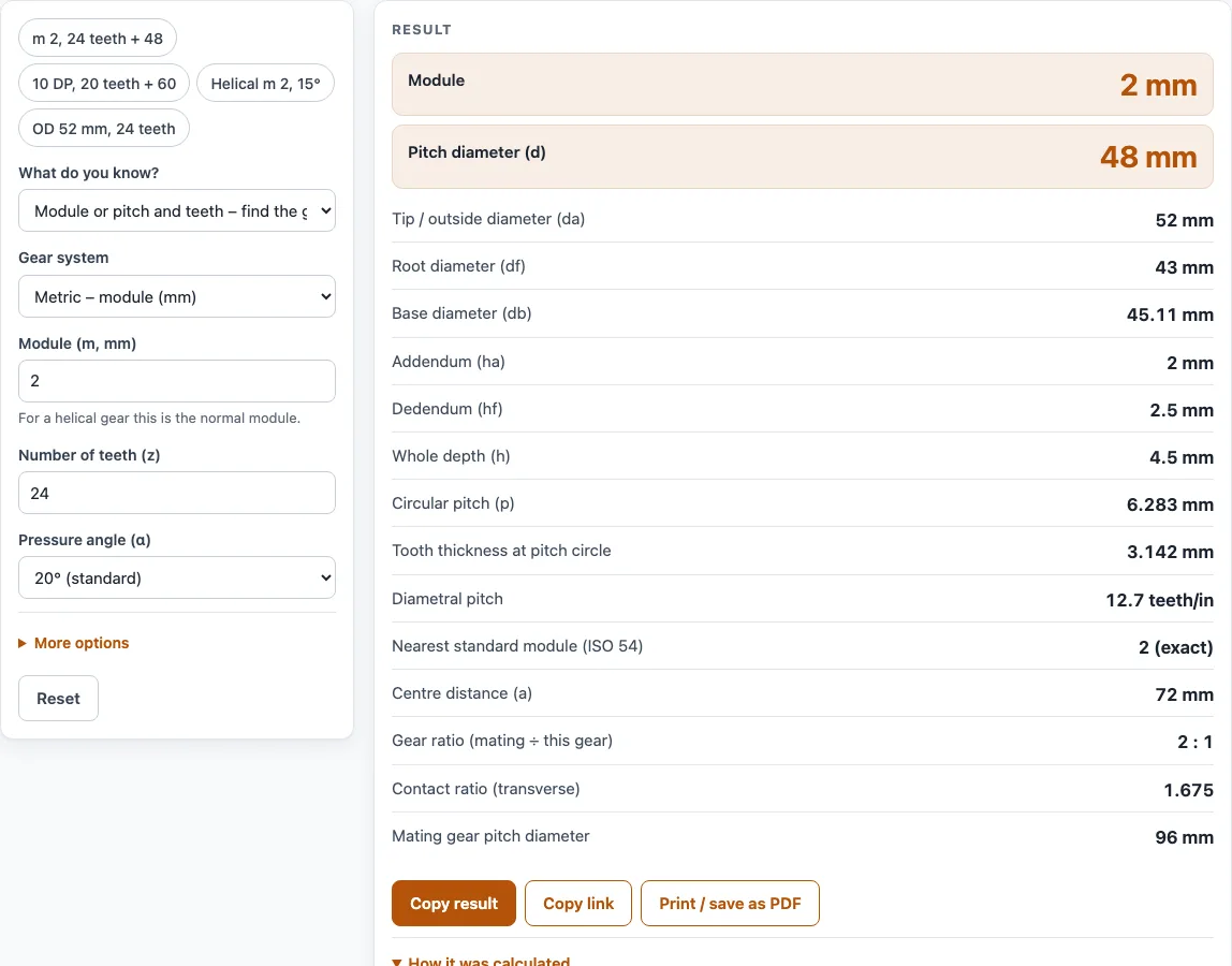
How to use the Spur Gear Calculator
- Under Gear system, choose metric or inch, then enter a module (metric, mm) or a diametral pitch (inch, teeth per inch). Each quantity has its own unit menu, so you can mix units if you need to.
- Enter the number of teeth. It must be a whole number of at least 3, and large enough to give a positive root diameter.
- Pick the pressure angle: 14.5, 20 or 25 degrees. The default is 20 degrees.
- Read the results. The module and diametral pitch are always both shown, along with the nearest ISO 54 module and how far yours is from it.
- If you know the outside diameter instead of the module, set What do you know? to Outside diameter and teeth. Enter the outside diameter and the number of teeth, and the tool returns the module.
- Open More options for less common cases. It holds the helix angle (0 to 60 degrees) for a helical gear, and the mating gear’s tooth count (default 48; leave it empty to skip) for centre distance, ratio and contact ratio.
- Check any warnings. These cover undercut, a contact ratio below 1 or a helix angle above 45 degrees.
- Use the preset buttons above the form to load typical cases, or press Reset to return to the starting example.
“How it was calculated” shows every formula with your numbers. Copy link keeps every input in the page address, and Print / save as PDF gives a dated record.
What is the gear module formula?
The gear module formula is m = d / z, where m is the module in millimetres, d is the pitch diameter in millimetres and z is the number of teeth. The module sets the size of the teeth, and two gears only mesh correctly when they share the same module and pressure angle. For example, a gear with 24 teeth and a module of 2 mm has a pitch diameter of 2 × 24 = 48 mm.
In inch sizes, the diametral pitch P is P = 25.4 / m, so a 2 mm module matches 12.7 teeth per inch. The module calculator uses a different starting point: m = da / (z + 2), where da is the outside (tip) diameter.
How do you calculate the pitch, tip and root diameters?
Once you know the module, the other dimensions follow from fixed rules. The pitch diameter is d = m × z. The tip (outside) diameter is da = d + 2m, and the root diameter is df = d − 2.5m. The addendum is 1 module, the dedendum is 1.25 module and the whole depth is 2.25 module. The tool uses this standard full-depth tooth, without profile shift, following ISO 21771. For module 2 with 24 teeth, d = 48 mm, da = 52 mm and df = 43 mm.
What do the base diameter and pressure angle do?
The base diameter is db = d × cos(α), where α is the pressure angle. The base circle is the circle from which the involute tooth profile is generated, so it sets the shape of the tooth. For module 2 with 24 teeth at 20 degrees, db is 45.105 mm.
A gear with fewer teeth than 2 / sin²(α) can be undercut when cut with a rack tool, which weakens the tooth root. The limit, rounded down, is 17 teeth at 20 degrees, 31 at 14.5 degrees and 11 at 25 degrees. The tool shows a warning when your tooth count is below this limit.
How does contact ratio show smooth meshing?
The contact ratio is the average number of tooth pairs in contact at once. It is calculated as (√(ra1² − rb1²) + √(ra2² − rb2²) − a sin α) / (π m cos α), where ra is the tip radius, rb is the base radius and a is the centre distance. The tool shows a warning below 1 and a notice below 1.2, which Shigley’s Mechanical Engineering Design gives as the minimum usually wanted for smooth running. For module 2, 24 teeth meshed with 48 teeth at 20 degrees, the centre distance is 72 mm and the contact ratio is 1.675.
Worked examples
| Input | Result |
|---|---|
| module 2, 24 teeth, 20° | module 2 (12.7 DP), pitch ⌀ 48 mm, tip ⌀ 52 mm, centre distance 72 mm |
| 10 DP, 20 teeth, 20° | module 2.54 (10 DP), pitch ⌀ 2 in, tip ⌀ 2.2 in, centre distance 4 in |
| module 2, 24 teeth, 20°, 15° helix | module 2 (12.7 DP), pitch ⌀ 49.69 mm, tip ⌀ 53.69 mm, centre distance 74.54 mm |
| 52 mm OD, 24 teeth | module 2 (12.7 DP), pitch ⌀ 48 mm, tip ⌀ 52 mm |
| 3 in OD, 28 teeth | module 2.54 (10 DP), pitch ⌀ 2.8 in, tip ⌀ 3 in |
Calculated by the tool above with these values.
Frequently asked questions
Can I use the results in commercial projects or client reports?
Yes. The results may be used in commercial work, including quotes, design notes, reports and client projects, without attribution.
Is the calculator free, and is anything I type uploaded?
The calculator is free and needs no account or sign-up. Everything is calculated in your browser, and nothing you type is uploaded.
Can I print or share a calculation?
Yes. Print / save as PDF creates a one-page record with the inputs, results, calculation steps and date. Copy link copies the page address, which stores your inputs in the ?s= part of the URL, so the same calculation can be reopened later or sent to a colleague.
Does the result certify that my gear meets a standard?
No. The tool does not certify compliance with any code. The result is for estimation, so verify critical designs against the applicable standard.
How do I find the module of an existing gear?
Count the teeth and measure the outside diameter, then use the outside-diameter mode: m = da ÷ (z + 2). For 24 teeth and a 52 mm outside diameter, the module is 2 mm.
Can I use diametral pitch instead of module?
Yes. Choose the inch gear system and enter the diametral pitch; the tool shows the equivalent module as well, using m = 25.4 ÷ P.
Related tools
- Bicycle Gear Calculator: use it when your question is about the gears on a bicycle rather than the size of one gear.
- Planetary Gear Ratio Calculator: use it when you need the ratio of a planetary gearset.
- Gear Ratio Calculator and Gear Ratio Finder: use it when you want the ratio between a driver and a driven gear.
- Axle Ratio Calculator: use it when you are checking the final drive ratio of an axle.
- All power transmission calculators: use it to browse the rest of the set.
Sources
ISO 21771 and ISO 54 (modules); Shigley’s Mechanical Engineering Design, ch. 13; full-depth tooth proportions per ANSI B6.1 as tabulated by Engineers Edge. For estimation; verify critical designs against the applicable standard.